Blue Noise Dithering
21 Sep 2022Initial seed pattern
This is a short description on blue noise dithering. For more detail see Robert Ulichney’s 1993 paper about blue noise dithering.
Initially a binary pattern BP is created where N pixels (about 10 percent) are set to 1 and the rest to 0.

The binary pattern then is convolved with the following filter function to generate the density array DA:
\[ \displaystyle f(x, y) = e ^ {-\frac{x^2+y^2}{2\sigma^2}} \]
You can use a sigma value of 1.5.
The convolution is wrapped around to facilitate a tileable result:
\[ \displaystyle DA(x, y) = \sum_{p=-M/2}^{M/2} \sum_{q=-M/2}^{M/2} BP((x-p)\ mod\ M, (y-q)\ mod\ M) f(p, q) \]
Maxima of the density array are called clusters and minima are called voids.
The 1 value in BP with the highest density value DA (tightest cluster) is set to 0 and DA is updated accordingly. Now the 0 value in BP with the lowest density value DA (largest void) is set to 1 (and DA is updated).
This is repeated until disolving the tightest cluster creates the largest void. This is done to spread the 1 values evenly.
Phase 1
In phase 1 of the dithering algorithm the 1 values of a copy of the seed pattern are removed one by one starting where the density DA is the highest. A copy of the density array DA is updated accordingly. The corresponding positions in the resulting dither array are set to N-1, N-2, …, 0.

Phase 2
In phase 2 starting with the seed pattern a mask is filled with 1 values where the density DA is the lowest. The density array DA is updated while filling in 1 values. Phase 2 stops when half of the values in the mask are 1. The corresponding positions in the dither array are set to N, N+1, …, (M * M) / 2 - 1
Phase 3
In phase 3 the density array DA is recomputed using the boolean negated mask from the previous phase (0 becomes 1 and 1 becomes 0). Now the mask is filled with 1 values where the density DA is the highest (clusters of 0s) always updating DA. Phase 3 stops when all the values in the mask are 1. The corresponding positions in the dither array are set to (M * M) / 2, …, M * M - 1.
Result
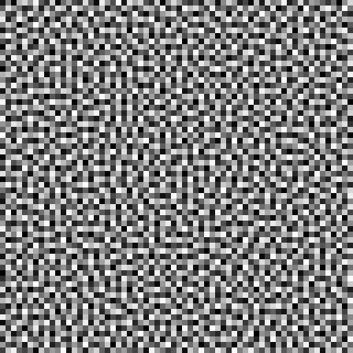
The result can be normalised to 0 to 255 in order to inspect it. The blue noise dither array looks as follows:
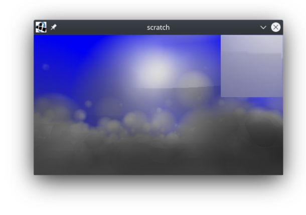
Here is an example with constant offsets when sampling 3D clouds without dithering.
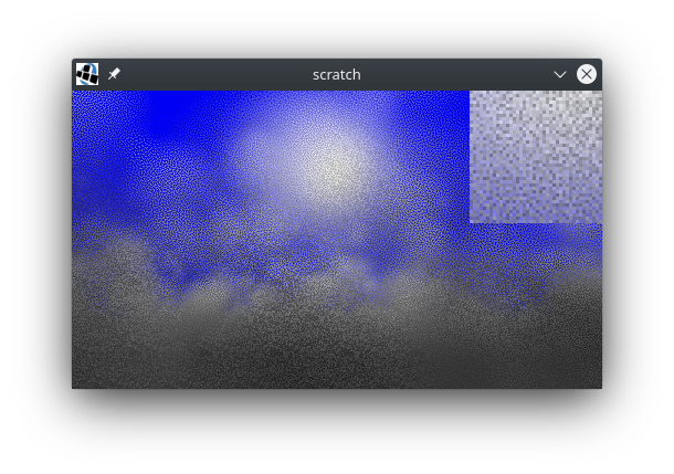
Here is the same scene using dithering to set the sampling offsets.
One can apply a blur filter to reduce the noise.
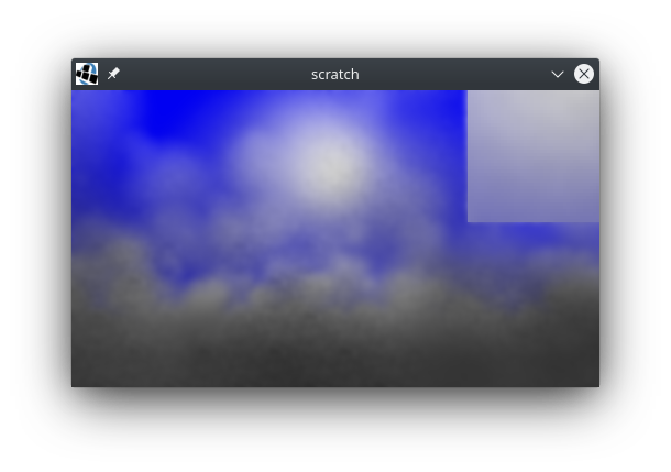
Note how the blurred image shows more detail than the image with constant offsets even though the sampling rate is the same.
Let me know any comments/suggestions in the comments below.